Introduction
The Aerofly tmEdit is a stand-alone fully offline program to create and modify Aerofly FS 2, Aerofly RC 8, RC 7 and RC 5 simulator aircraft files. It is the ideal companion to bridge the gap between the 3D model and the Aerofly aircraft implementation and assists with the Aerofly TMD file coding by debugging and powerful 3D editing capabilities.
Feature Overview
The Basics
Opening files
Supported File Extensions
TMC, TMD, TME, TSC, TGI, TGI.TXT (aerofly specific)
OBJ and MQO (typical 3D model) file types are supported.
The tmEdit software supports mainly the Aerofly aircraft definition file *.tmd text file format for editing Aerofly FS and Aerofly RC aircraft.
It can read *.tmc and *.tsc files as well and theoretically supports all files with the typical Aerofly syntax as seen in the Aerofly FS 1, Aerofly FS 2, Aerofly RC 5, Aerofly RC 7 and Aerofly RC 8.
The editor can also load 3D models in form of Aerofly FS 2 intermediate geometry files (*.tgi and *.tgi.txt), Metasequoia 3D model files (*.mqo) and Wavefront *.obj files.
Files are opened in conventional ways with a open file dialog, just like any other editor you have ever used 😉 Also supports Windows file assignments.
The program can also be opened from the windows context menu via “Open with…” -> “Choose another app”. You can also select to “Always use this app to open .tmd files”. The program will open and load the selected file.
Recent Files
Recently opened files are saved and the last opened file or project is automatically restored when tmEdit opens next time. When opening a file the open file dialog automatically remembers the last folder location as well. To suppress opening the last opened file there is an option in the program settings. To remove a recently opened file you can middle-click the item from the drop down menu. To clear the entire list you can select from the main menu: Project -> Recent -> (at the very bottom) Clear this list.
To open a recent file you can click the down arrow next to the open button and select the file or use the main menu: Project -> Recent -> select the desired file.
Projects
A tmEdit project can be saved as a TME text file. Loading a project opens the aircraft and 3D models and project specific settings.
A project in tmEdit is a single file which is saved in the Aerofly syntax with the *.tme file extension.
A projects consist of the file path link to a TMD file and 3D model, the selected last camera positions, aircraft specific settings such as the mean aerodynamic chord datum definition, selected airfoil data and assigned geometry functions (see below).
After loading an aircraft TMD file and a 3D model you can save the tmEdit project to any location.
Input Gestures
The most common input gestures/shortcut keys in tmEdit are:
| Shortcut | Executed command |
|---|---|
| Alt + F4 | Closes the program |
| Ctrl + O | Shows the open file dialog |
| Ctrl + S | Save the project and all opened files. |
| Ctrl + Shift + S | Save project as… |
| Ctrl + C | Copy selected object to the clipboard |
| Ctrl + V | Paste an object from clipboard |
| Ctrl + D | Duplicate selected object |
| Ctrl + X | Copy selected object to clipboard and delete it from the TMD |
| Delete | Delete the selected object |
| Ctrl + Z | Undo |
| Ctrl + Y | Redo |
| F1 | Opens Aerofly FS Wiki in default browser |
| F2 | Opens the about window with links to support page (this page), frequently asked questions (FAQ) and license information |
| F3 | Search for objects |
| F4 | Show window to assign functions to individual geometries (to add switches and buttons fully automatic) |
| F5 | Quick reload of current files (excluding 3D models) |
| F6 | Show overview (e.g. total mass, CG, estimated stall speed) |
| F7 | Open debugger window |
| F12 | Program settings and preferences |
| Ctrl + F | Search for objects (same as F3) |
| Ctrl + Q | Center the view on the selected object |
| Ctrl + W | Toggle the wire-frame mode for geometries |
| Ctrl + E | Select a pivot and axis from the selected geometry |
| Ctrl + R | (or just R in 3D window) Rotate the selected object |
| Ctrl + T | Edit the stations of an aerowing or aerofuselage |
| Ctrl + L | Scale the selected object |
| Ctrl + M | (or just M in 3D window) Move the selected object |
| Ctrl + K | (or just K in 3D window) Select the knife-cut tool (for adding aerowing and aerofuselage stations) |
| Ctrl + I | (or just I in 3D window) Mirror the selected object on the aircraft symmetry plane. |
| Ctrl + Space | If a geometry is selected: hide it. If nothing is selected: toggle the visibilty of all geometry. |
| Ctrl + Shift + A | Show all geometries |
| Ctrl + G | Open the tmGenerator window to generate new objects based on the selected geometry (e.g. automatically generate an aerowing, fuselage, wheel or button/switch) |
| Ctrl + U | |
| 1 and Shift + 1 | (in 3D only) Select the first camera category (cockpit), then loop between them. Press multiple time to select other cockpit cameras |
| 2 and Shift + 2 | (in 3D only) Select the second camera category (follow cameras), then loop between them |
| 3 and Shift + 3 | (in 3D only) Select the third camera category (pan around cameras), then switch between them |
| C and Shift + C | (in 3D only) Switch the camera |
| T and Shift + T | (in 3D only) Change the internal time of day (e.g. to change the light position or to make the light maps of the 3D model more visible) |
3D View
Hold down the Ctrl key and use the mouse wheel to quickly switch between the different display modes.
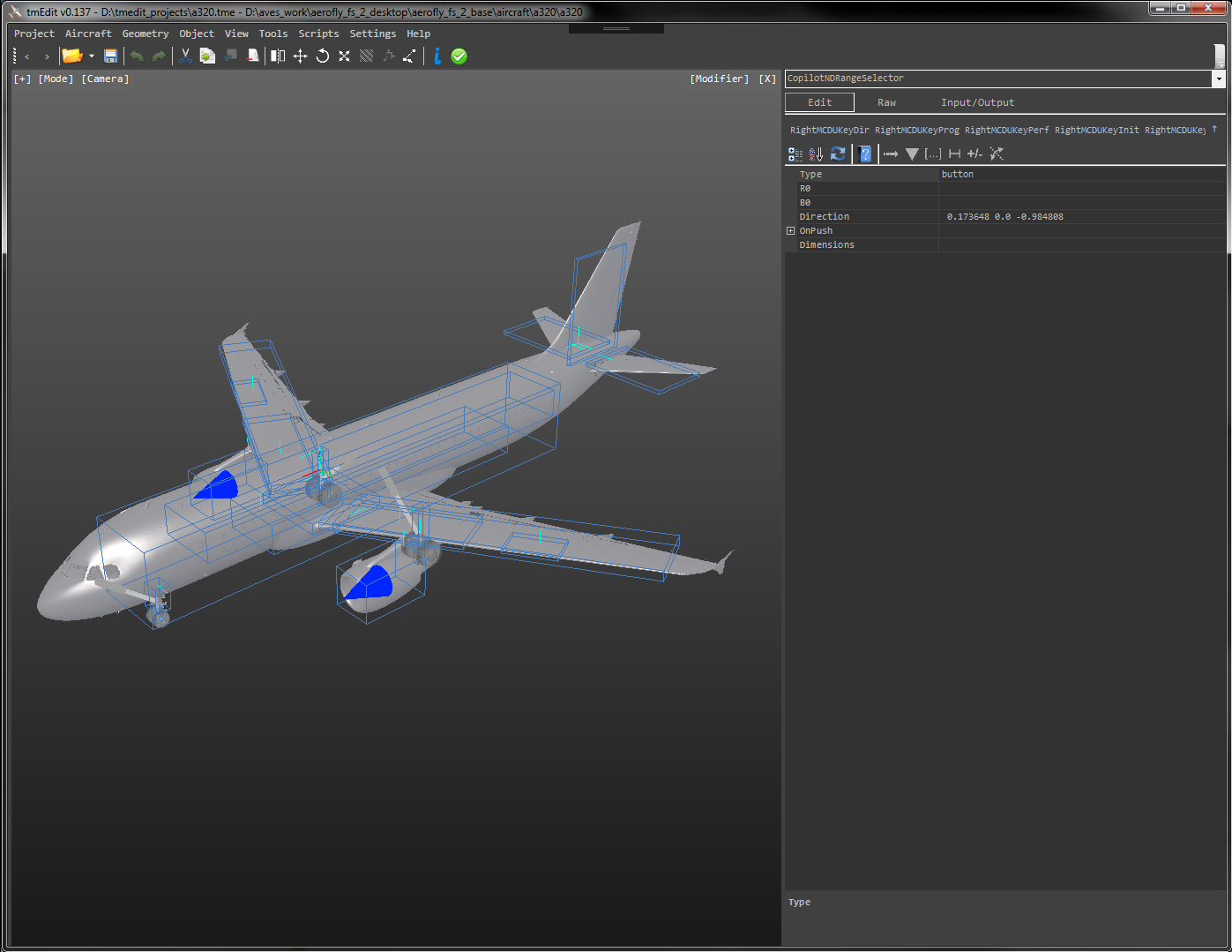
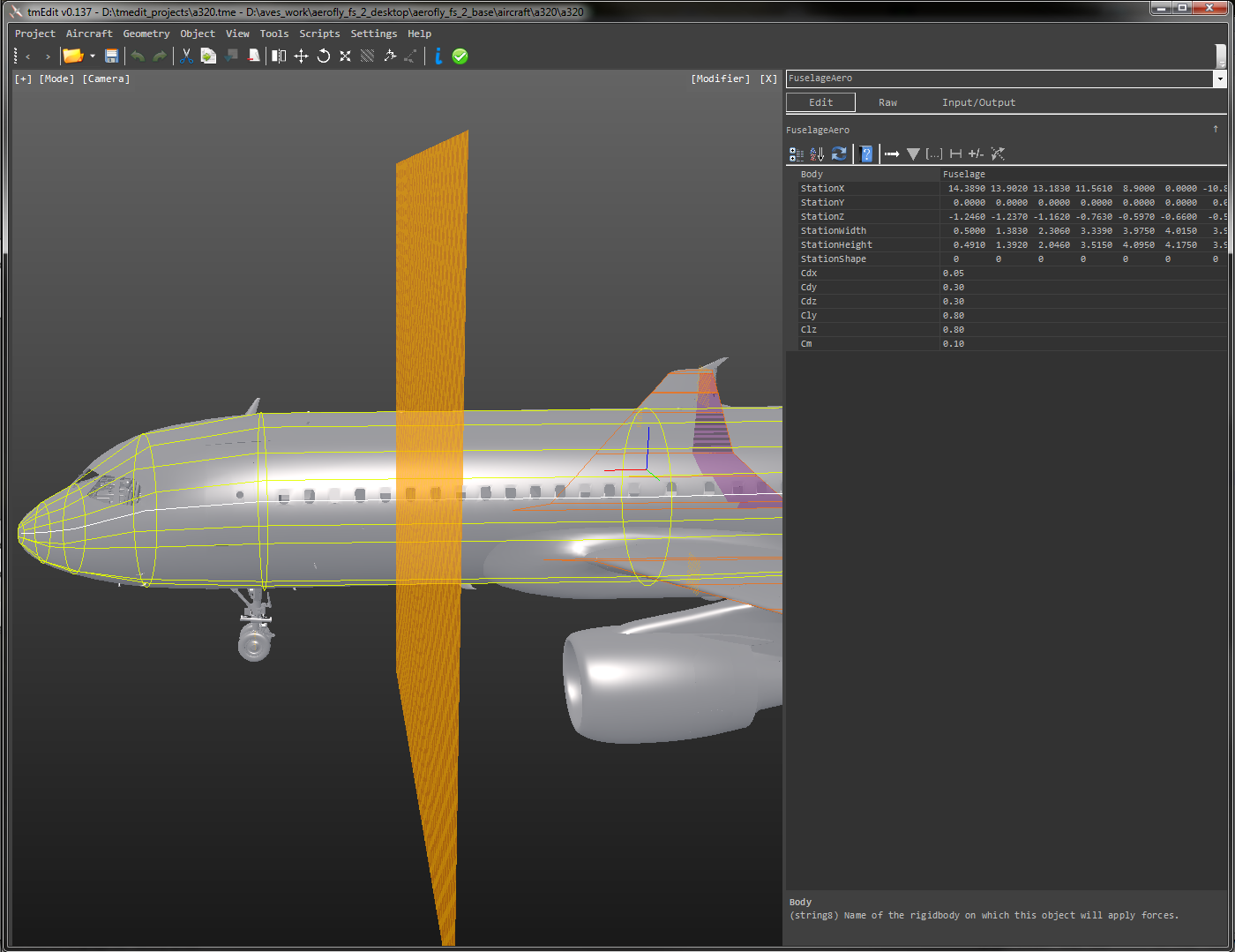
Once an aircraft TMD file is opened you can see the physical geometry of the wings as a red/orange outline, the rigidbodies in light blue, the aerodynamic fuselage in yellow, wheels, propellers, airbrakes and so on.
There are multiple display modes of this view. Hold down the Ctrl key on your keyboard and scroll down with your mouse wheel to change the display mode or use the [Mode] button in the top left corner to display a dropdown menu.
Available display modes are:
- Dynamics – All objects in the DynamicsObjects section of the TMD file.
- Rigidbodies – Rigidbodies, joints and actuators only.
- Aerodynamics – Aerowings, aerofuselages and airbrakes only
- Controls – controls.tmd 3D clickspots as boxes, spheres, cylinders and clipped cylinders and their transformations
- Graphics – 3D-representable objects of the GraphicObjects section of the TMD file.
- Model – Raw 3D model geometry selection
Click on the little [+] button in the top left corner to show options for the currently selected mode. You can hide individual groups of objects or toggle the texture and wireframe mode (use Ctrl + W).
3D View Controls
View controls are imitating the Aerofly FS 2 view controls.
- Hold down the left mouse button and move the mouse to rotate the view.
- Use the mouse wheel to zoom.
- Hold down the middle mouse button to move the view (or hold Shift + move the mouse).
- Change the field of view with Shift + Mouse-Wheel.
You a can also cycle through the views with the keys 1 … 3 (Shift + 1 … 3) as well as key c and Shift + C and change the time of day with T and shift + T.
Selecting Objects
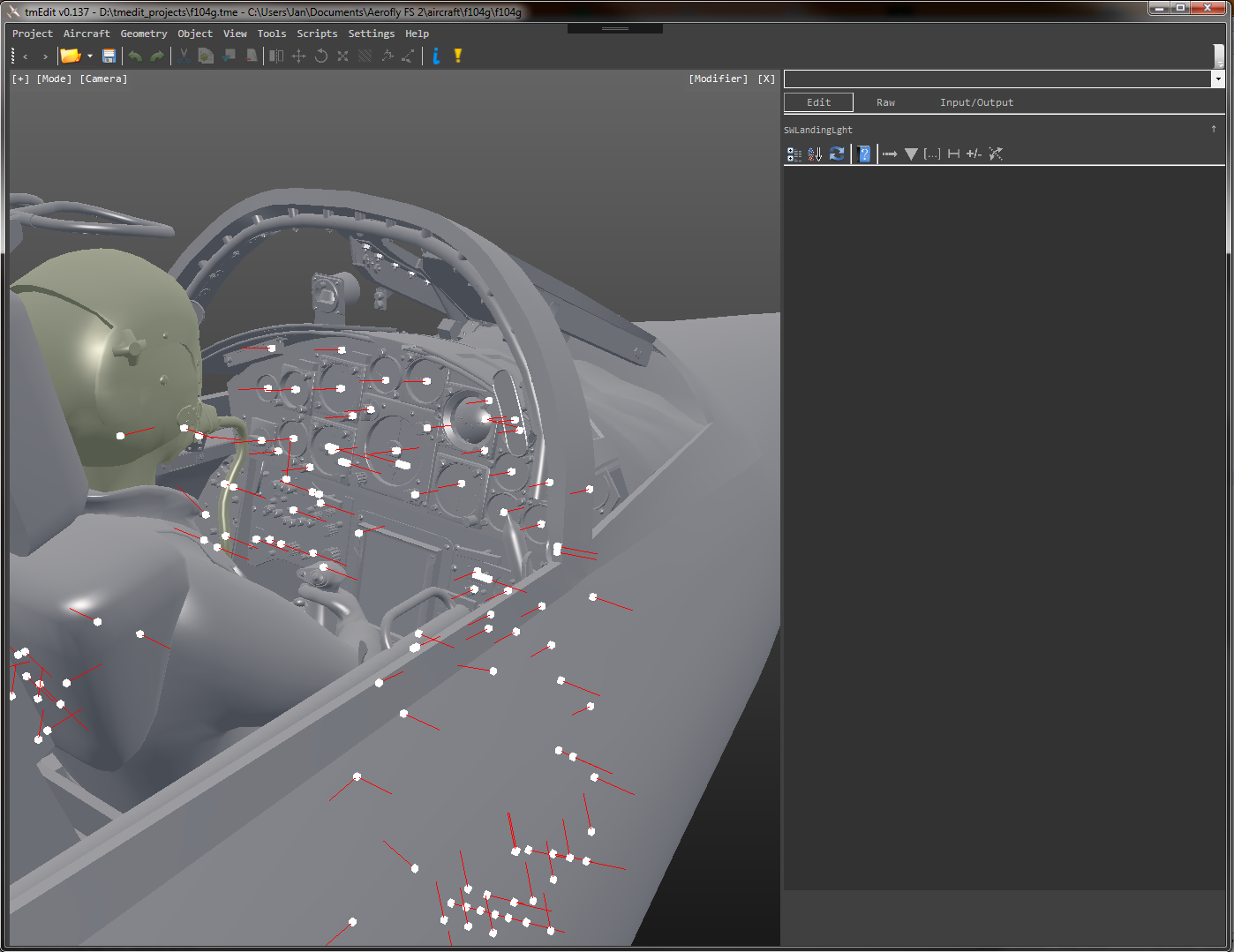
Left click to select object in 3D view.
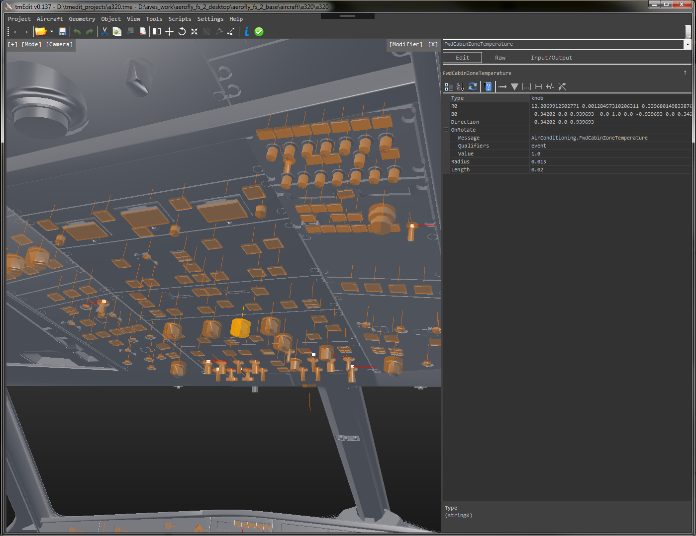
When you move your cursor over an object it is highlighted. Selecting an object is as easy as pointing at it in the 3D view and left clicking. Make sure to hold the mouse still, otherwise you just start rotating the camera.
Once the object is selected it will remain highlighted with a green color.
The objects that are displayed and can be selected depending on the currently selected display mode. Hold down the Ctrl key and use the mouse wheel to change that mode. Only objects that are highlighted when the mouse is over them can also be selected in that mode.
Mouse X-buttons supported to undo the selection
If your mouse has additional buttons to navigate back and forth (mouse x-buttons) you can use them to undo/redo the selection of objects and re-select the previously selected objects. If you accidentally miss-clicked you can undo that. There are also buttons in the tool strip menu to achieve this: “<" and ">” for users that don’t have these buttons on the mouse. There are also main menu options for this listed under “Object”.
Other methods to select an object:
- From the debugger double click an entry to select the affected object.
- From the search press Ctrl + F and start typing the object name that you wish to select. The auto-complete will suggest existing object names. Confirm with enter to select the object. You can also drop down this list and select the object that way.
- From the references when an object uses the output of another object you can follow that reference by right clicking in the properties window (on the left hand side) and select “follow reference”. You can also double click the list items in the input/output list boxes at the bottom right.
Multi-Edit also available!
To select multiple object at the same time hold down the Ctrl key before clicking on another object.
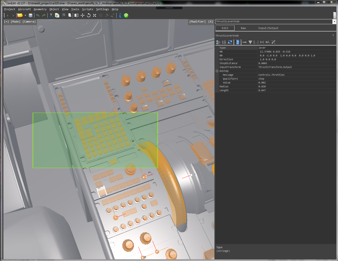
You can also select multiple objects within a rectangle on the screen by holding down the the Shift + Alt keys and then draw a rectangle with the mouse. Any object that falls within that rectangle will be added to the selection.
You can use consecutive rectangles to trim away already selected objects or hold down the Ctrl key and click objects to remove them from the selection. You can undo each selection step with the mouse x-buttons or toolstrip buttons as described above.
Overview
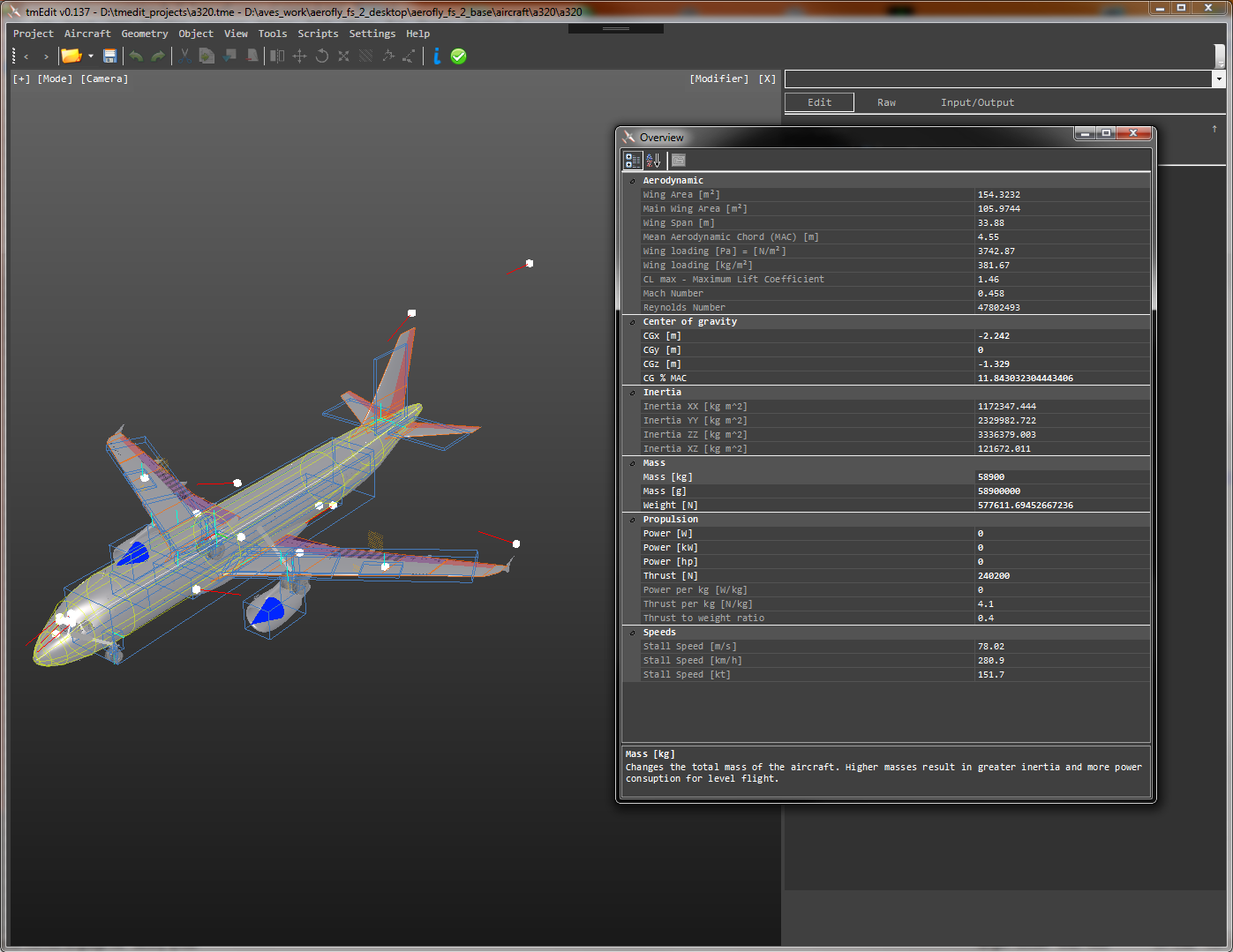
The overview shows and let’s you edit the total mass, center of gravity and more.
The overview window can be opened with the F6 key. A sorted property grid appears that calculates some key values like the total mass of the physic objects within the TMD, the center of gravity (CG), the total wing area, CG in percent of the mean aerodynamic chord (stability measure) and estimated values for stall speed, Mach number, Reynolds number, thrust to weight ratio and computed inertia tensor values.
The CG position (x = forward, y = left, z = up) can be entered directly and the program will try to move the rigidbody “Fuselage” until the cg is set to the position you entered.
When editing the CG % MAC value (center of gravity relative to the mean aerodynamic chord leading edge = LEMAC and mean aerodynamic chord length = MAC) make sure that you have set up the MAC and LEMAC correctly. You can open these settings from the main menu: Aircraft -> Define mean aerodynamic chord. Per default it auto-detects the LEMAC and MAC but that position may not correlate to the position defined by the aircraft manufacturer! Enter the LEMAC and MAC in meters relative to the aircraft 3D model origin.
Modifier
tmEdit has a lot of tools to modify the selected objects. It can mirror an object from left to right (or vice versa), move/rotate/scale an object, edit aerowings and aerofuselages and create new stations with a knife cut. With a geometry selected you can also pick a new rotation axis and pivot.
Mirror
Mirror the selected objects from left to right (or right to left) by pressing Ctrl + I
The mirror modifier allows you to copy changes made on one side over to the other side. E.g. you could modify the wing geometry on the left and then update the right side accordingly. Internally this modifier always tries to find a mirror counterpart. It replaces position attributes like “Left/Right” and “Pilot/Copilot” within the object’s names and all of its parameters.
When there is no mirror counterpart it creates it and adds it underneath the last of the selected objects in the TMD file.
To mirror an object it needs to be select it first. Then click the mirror toolbar icon or right click in the 3D view and select “Mirror”, use the main menu: Object -> Mirror selected; or press the short-cut “Ctrl + I”. You can also use the [Modifier] button in the top right corner of the 3D view and select “Mirror” from the drop down.
Move
Start moving the selected objects with Ctrl + M. Grab the 3D handle and drag the objects with your mouse.
The selected objects can be moved with the move modifier. After selecting an object press the move icon in the toolbar or right click the 3D scene and select “Move” from the context menu. From the main menu you can also select Object -> Move or press the short-cut “Ctrl + M”. Pressing the [Modifier] button in the top right opens a drop down menu where you can also select the “Move” function.
Once the modifier is active you can press the “Esc” key to close it or press the [X] in the top right of the 3D view to close it.
If you press Ctrl + M a second time you can move the objects along their local orientation vectors
Sometimes it’s required to move objects along a panel surface or perpendicular to it. When the move modifier is already active you can press Ctrl + M again to toggle between global orientation or local object orientation. You can also toggle the mode with a checkbox on the move modifier panel. E.g. if a clickspot is already aligned with the panel you can move it along the rotated coordinate system.
Please note that you can only move objects with a position attribute (e.g. “R0” or “Pivot”). Complex geometries such as aerofuselages or aerowings are moved as a whole. To modify individual stations use the station modifier.
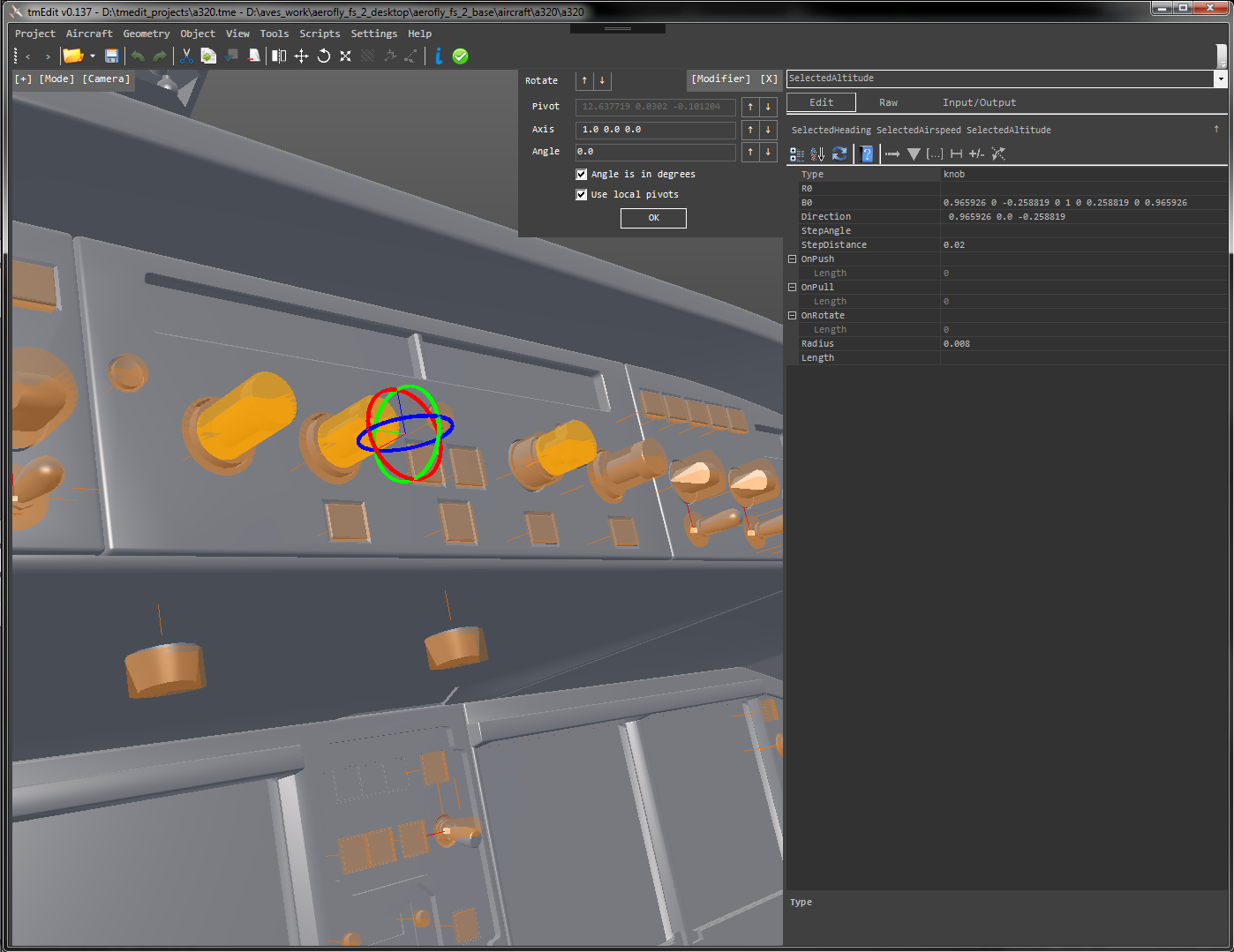
Rotate
Ctrl + R starts the rotate modifier. Simply rotate the selected objects by dragging the ring handles.
The rotate modifier is accessible through the main menu, the [Modifier] drop down or with the short-cut Ctrl + R.
The selected objects can be rotated either together as a whole or each around its own center. These two modes are toggled by pressing Ctrl + R or by using the checkbox on the panel. A set of three rings appears at the center of the selected object(s). Drag one of the rings to rotate around the x, y or z axis.
Please note that you can only rotate objects that have an orientation property in the TMD (e.g. “B0” or “Axis”). You can’t directly rotate geometries for example as they are not editable with this TMD editor.
Scale
Scale objects with Ctrl + L.
A handful of objects can also be resized with the scale modifier. This includes aerowings, aerofuselages but also control clickspots from the controls.tmd file. After selecting the object(s) that you want to scale press Ctrl + L or select the modifier from the main menu or [Modifier] drop down. Any following presses of Ctrl + L toggle between scaling along local axes and global scaling. You can also use the checkbox on the scale modifier panel to toggle this mode.
Note: To scale individual stations of an aerowing or aerofuselage please use the station edit modifier.
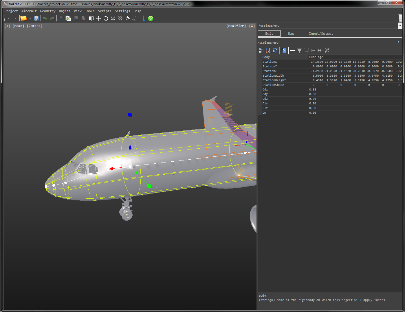
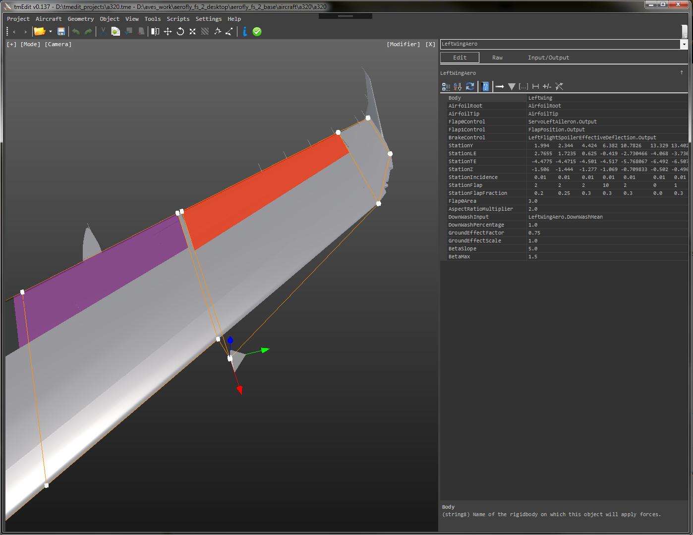
Editing Aerofuselage and Aerowing Stations
Select a wing or fuselage and press Ctrl + T to start editing them
tmEdit enables the modification of the aerodynamic wing geometry and aerodynamic fuselage geometry with easy to use mouse-dragging. The modifier is started from the main menu, the [Modifier] drop-down or with the short-cut Ctrl + T. White boxes will appear around the wing outline or in the center line of the fuselage.
For wings simply click on the vertex that you want to edit and then use the move handle to drag it around.
Please note that moving a vertex perpendicular to the span-wise direction will also cause the trailing edge vertex (or leading edge vertex) to move too. This is due to the geometric definition of the aerowing itself. They share the same coordinates for Y and Z and thus changing either of these values affects both the leading edge and the trailing point. To increase the incidence please edit the StationIncidence property directly. There is no modifier for this specific purpose yet.
For fuselages a secondary set of handles appears on the left and on the top of the station. You can drag these to change the width and height of the station directly. Please note that negative values should be avoided.
To change the shape of the station from round to rectangular please edit the StationShape parameter directly.
Pressing the Del-key removes the currently selected station
Knife-Cut
Cut the aerofuselage or aerowing with a knife by pressing Ctrl + K and then left clicking. If you have geometries selected the cut will fit a new station on them at the selected position.
To create new stations on an aerowing of aerofuselage you can use the knife cut tool.
If you wish to fit the wing on a geometry please select the all geometries that belong to the wing first. E.g. select the geometry for the wing, aileron, flap and slat in the model mode (use Ctrl + Mouse-Wheel and scroll down to change the mode). Then switch back to the physics mode (Ctrl + Scroll-Wheel again). If you don’t want to use any geometries then switch to the model mode and left click the background to deselect any geometries.
To perform a knife cut select on the fuselage or wing and start the knife cut from the main menu, the [Modifier] button in the top right corner or by pressing Ctrl + K. Move the mouse to move the cutting plane. Press left click to perform a cut or the ESC key to cancel.
When geometries were selected the modifier will try to create a station that fits on the geometry.
If you cut through a wing the leading and trailing edge will be detected automatically and the station flap fraction will be calculated as well if the cut intersects a geometry names “Aileron” or “Flap”. The algorithm will also try to snap to a nearby group of vertices in the 3D geometry. Without any geometry selected the cut will create a linear interpolation or extrapolation if cut is outside the current wing geometry.
If you cut an aerofuselage with a geometry selected it will use the maximum left/right and up/down dimensions to calculate the mid point and the width and height. Depending on the shape of the geometry at the selected position the resulting station could be round or rectangular in shape. When you cut a fuselage without a geometry selected it will linear-interpolate (or extrapolate) the fuselage position, width, height and shape. When the two stations are not identical in shape the close one will be used.
To change the shape of an aerofuselage station from round to rectangular or the other way round please change the StationShape property directly.
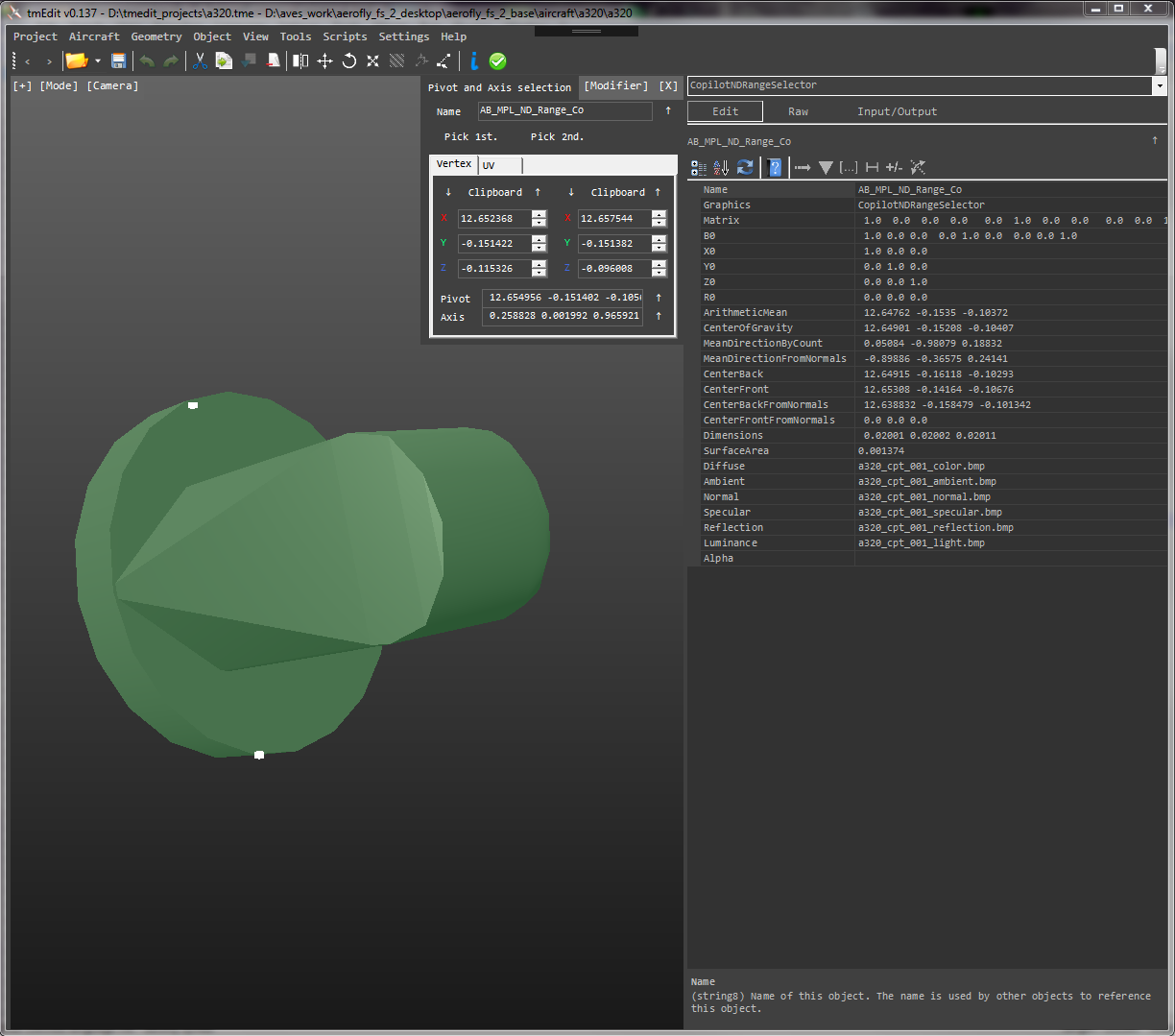
Axis and Pivot Selection
Pick vertices from the 3D geometry to create new axes or pivots. Press Ctrl + E to start
Switch to the model display mode or graphics display mode in the 3D view by holding down the Ctrl key and rotating the mouse wheel down. You can also click the [Mode] button in the top left of the 3D view and select the mode directly. In that mode select a geometry or multiple geometries (hold down Ctrl key). After selecting the geometries press Ctrl + E to start the modifier.
To center the view on the selected geometries press Ctrl + Q. To toggle between wire-frame mode and surface mode press Ctrl + W.
The key combo Ctrl + Q, Ctrl + W and Ctrl + E is very common here…
When you hover over a vertex of the geometry a white box appears on it. Left click to select your first point. The modifier now keeps the first point and automatically switches to the second vertex. Move the mouse over the second vertex and left click again. When you miss-clicked you can restart by pressing Ctrl + E again or by clicking the buttons “Point 1” or “Point 2”.
When finished you can either apply the selected Axis and Pivot directly or you can copy them to the clip-board with the little buttons with an up arrow next to the result textboxes.
If you need to insert a vertex from the clipboard you can also easily do that with the down-arrow button above the Vertex 1 or Vertex 2 numeric input boxes.
If you press the “Apply” button the editor will apply the axis/pivot directly if the selected object is a hingedbodygraphics object for example. If the selected object does not have properties like Axis or Pivot/R0 it tries to find an assigned “InputTransform” object, e.g. on a rigidbody or bendingbody graphics object. The axis and pivot are then applied to the object specified in the InputTransform property instead. This makes it possible to select a rigidbodygraphics in the graphics display mode, pick an axis and pivot and then apply these to the transformation of the selected object.
Use the Esc button to close the modifier or the little X in the top right of the modifier panel when finished.
The axis and pivot tool also allows the selection of UV coordinates.
Use the tab control on the modifier panel to see the UV coordinate output of the selected vertices. You can change the slider to match your texture resolution to get texture the coordinates of the selected vertices in pixels (from the lower left corner).
Detecting and Assigning Unreferenced Geometries
Geometries that have not been used in any GeometryList in the graphics section are highlighted in red per default. You can change this by clicking the [+] button in the top left corner of the 3D view to open the drop down followed by a click on the “highlight unreferenced geometries” checkbox.
When an unreferenced geometry is selected a red message appears in above the property grid. Simply select a graphics object from the drop-down to add the selected geometry to its GeometryList.
Because unreferenced geometries are not game-breaking they are a mere information result in the debugger output. If you open the debugger and select the model debug option (top right “Model” button) and refresh the test you may see a list of unreferenced geometries in the debug output. Right-click this message and select to copy everything between the quotation marks to copy the list of all unrefrenced objects to the clipboard. Then select a graphics object with a GeometryList property and paste that list at the end of the property to add all object this way.
Tools
tmEdit has a main menu option to quickly launch some stand alone tools. These executables can be downloaded and executed separately and the menu links are just short-cuts for the user.
Unit Calculator
Simple and stress free unit conversions.
The unit calculator is a small program that allows you to quickly convert values between units. It has the most commonly used units in aviation such as pounds, feet, inches, horse-power, pound-torque, revolutions per minute, etc. and compute the standard unit outputs or vice versa. Simply type or copy paste the input value on the left. Then use the drop down menu at the top to pick a category. Then select the input unit of the left drop down underneath the input value field. And select the output value unit on the right drop down. Press calculate to see the result in the right textbox. Highlight the result and copy it to the clipboard for further use.
The switch button in the middle swaps the input and output units.
Stand-Alone Offline Physics Unit-Calculator
Rotation Matrix Generator
When a precise orientation matters.
The rotation matrix generator allows you to create 3D matrices from three Euler angles in degrees or radiant. Type in the rotation angle(s), confirm the order of rotation on the right (per default rotation around Z axis first, then rotation around Y axis and rotation around X-axis last. Click on the 1st, 2nd or 3rd radio-boxes to change the order of rotation.
Press the compute button to see the results. The 3D matrix is output in the matrix field. This is purely a debug output for you.
Underneath you can see the X0, Y0 and Z0 axes of the matrix as used in Aerofly FS. At the bottom you see the output B0 matrix which can be used for rigidbody orientations or for clickspot orientations. The little up arrow button the lower right copies the B0 textbox string to your clipboard.
Stand-Alone Offline Rotation Matrix Generator
Color Picker
Create colors with a handy color picker.
This basic tool uses the the well known color picker tool to pick a color and it then calculates the normalized color values for the use in the TMD by dividing the RGB values each by 255.
A slider for the transparency controls the alpha channel.
Advanced Features
Animation
tmEdit can now animate graphics objects!
An animation slider in the lower right corner is used to debug all graphics transformations including graphics_translation, graphics_rotation, hingedbodygraphics, movinggraphics and more. Objects that are not correctly linked together will simply not move. Press the “Update Links” button to make sure… And if that doesn’t help the debugger may have an insight on why an object that should move does not 😉
The checkbox allow you to toggle the animation on and off. The button “0” and “1” move the slider all the way without the need to drag the slider itself.
The “Update Links” button is used to force an update in the internal linking between the objects. This may be required if you assign a new geometry to a GeometryList property or when you changed a property like the InputTransform object reference.
Geometry Function Assignments
With tmEdit you can semi-automate the creation of buttons and switches in your aircraft.
A powerful batch script tool is the geometry function assignment window. This batch tool creates several hundred buttons or switches with the click of a button. It requires some manual input depending on how well the 3D model geometries were named or how common they are. The scripts rely heavily on a correct object naming convention in the 3D model (e.g. full names like “Aileron”, “Switch…” (or “Sw”), “Button…” (or “Btn”), “Left”/”Right” etc. and either correctly set-up object pivots in the 3D model or no local pivots what so ever. The camera positions of the pilot and copilot seat should also be checked before the scripts are executed because they are being used to determine the correct knob rotation and panel forward, up and down directions (i.e. panel surface normals usually pointing towards the pilot camera).
Press F4 to open the Geometry Function Assignment window and populate the table.
Then either populate the list with the selected geometries, the unreferenced geometries or all geometries. These actions don’t have an immediate effect, so you can basically add and delete geometries to this list as long as you want. If you save the tmEdit project this list will be saved for next time as well.
Once all geometries that you want to be handled automatically are added to the list go through the rest of the table and fill in a name for the things inside the TMD (e.g. it should be called “SwitchMasterGenerator” in the second column and not “Sw_Gen01”, add a message name if needed (e.g. “Electrical.MasterGenerator”) and change the assigned function with the drop-down on the right if needed. You can also change the assignments for multiple geometries if you select them all in the table (hold down Ctrl key) and pick the function from the drop-down at the top.
Save the project and create a backup of the TMD.
Once you are happy with your setup save the project. Create a good backup of your TMD files. Then press the “Run Script” button to let tmEdit do it’s magic. It should be completed within a second or two and the changes should be visible in the different display modes. E.g. in the controls.tmd display mode you should see new clickspots, in the graphics you should see new objects and the animation slider should now correctly animate all of the new geometries.
Click “Run Script”, save all files and test the results.
Save all files with Ctrl + S.
For the all-or-nothing user: Open Aerofly and check if it works. If you see a red-box or when the default aircraft (C172) is loaded instead, please check the tm.log file for errors and also check if the tmEdit debugger picks up on any errors.
Optional for the more cautions user: Compare the current TMD file with the backup before the scripts were executed.
Manual work that may be required: Some rotation axes may be incorrect. Especially if the 3D model had no proper local pivots and rotation axes set up.
Scripts
Simply select a geometry and press Ctrl + G to open the tmGenerator window
Some of the scripts used in the geometry function assignments can also be executed directly. This is particularly useful if you quickly want to create an aerowing or a switch with a clickbox, etc.
Select the desired output on the left and fill in the name and message name if needed. The results should now be previewed on the right. Check the checkboxes on the parts that you want to edit (e.g. you can leave out the controls.tmd for example), then add the results. Save all files when finished.